Enabling CAN Bus Support on the Embedded Linux Development Board
| SR NO | Chapter | Page Num |
|---|---|---|
| 1 | Hardware selection and connection | This covers the basics of choosing the right hardware components and ensuring proper connections to ensure optimal performance. |
| 2 | Linux Driver & Userspace Program and CLE | In this, you’ll learn about Linux drivers, the communication between user space and the kernel, and how to utilize the Command Line Environment (CLE). |
| 3 | Rough | This section may be under development or covers an initial overview of the topic. |
1. Introduction
For this tutorial, we will be using the MYIR Tech Development Board. Specifically, the following:
- MYD-C8MMX-V2 Development Board, which is based on the Arm Cortex-A53 NXP i.MX 8M Mini Quad Application.
- System on Module (SOM): MYIR Tech SOM.
2. CAN Bus Modules
The following CAN modules are recommended. You can choose one of them:
- MCP2515 CAN Bus Module with TJA1050 Transceiver:
- Serial CAN Bus Module (based on MCP2551 and MCP2515):
3. Required ICs for CAN Bus Support
To enable CAN bus support on Linux boards, the following two ICs are required to establish communication between the system and the physical CAN bus network:
- CAN Bus Controller
- CAN Bus Transceiver
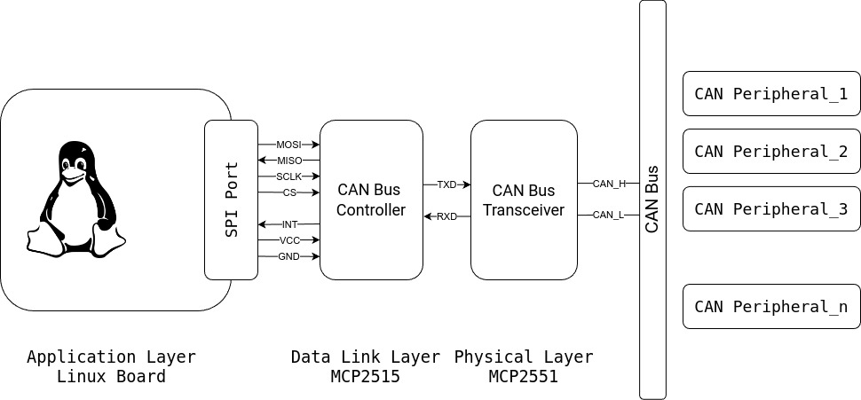
1. CAN Bus Controller
Function:
- Handles higher-level CAN protocol operations (message framing, bit timing, error handling, message filtering).
- Manages transmission and reception of messages over the CAN network.
Interface:
- Communicates with a microcontroller via SPI (Serial Peripheral Interface) bus.
- Does not directly connect to the physical CAN bus.
Most common: MCP2515
2. CAN Bus Transceiver
Function:
- Manages the physical layer of CAN communication by converting digital signals to differential signals for the CAN bus.
- Ensures signal robustness for transmission over longer distances and in noisy environments.
Interface:
- Connects to the CAN bus physical wires (CAN_H and CAN_L).
- Interfaces with the MCP2515 via TXD (transmit data) and RXD (receive data) pins.
Most common: TJA1050, MCP2551
- Capacity: 112 nodes (45 Ohm)
- Not recommended for new designs: see new IC
- TJA1050 module
Why Two ICs Are Needed
Best Transceiver: MCP2561
Note: MCP2551 is not recommended for new designs; use MCP2561 instead.
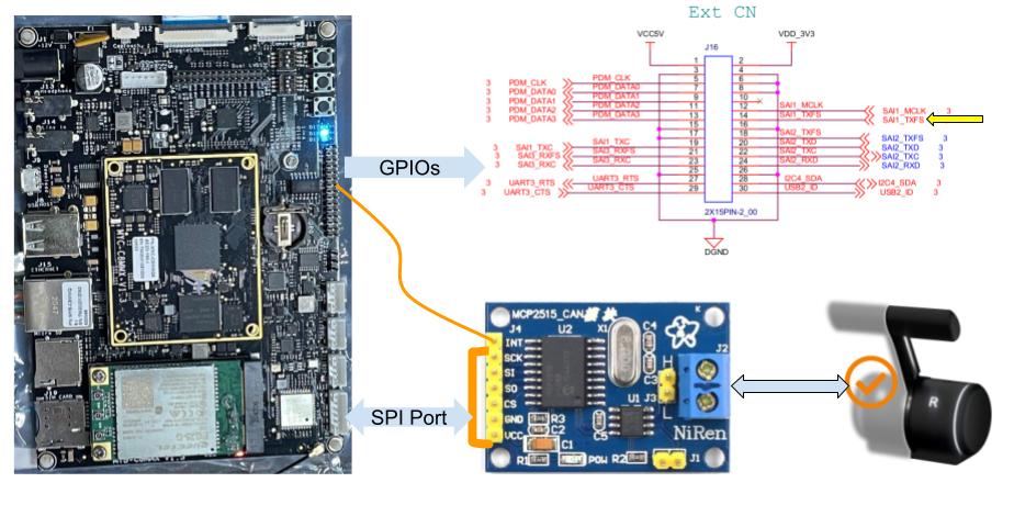
Modules and Wiring
Many modules are available. Make sure they match the required configuration.
- Connect the module based on DTS pin and confirm with CAN SPI transceiver.
- For out of 9 manufacturing modules, the two best are: Microchip (MCP251x) and Third-party Serial (slcan).
Wiring Instructions
Before proceeding, set up a serial console. For more details, refer to this link: {Insert Link}
Note: Be careful about power pins (VCC, GND). Incorrect connections can easily damage the board.
Find the SPI pins on the development board (on MYIR Tech board, pin names are written on the back of the c8mmx board).
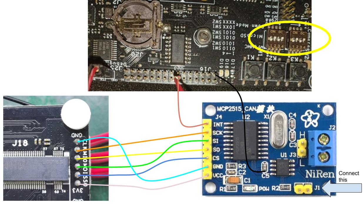
Pin to Pin Connection Between c8mmx and MCP2515
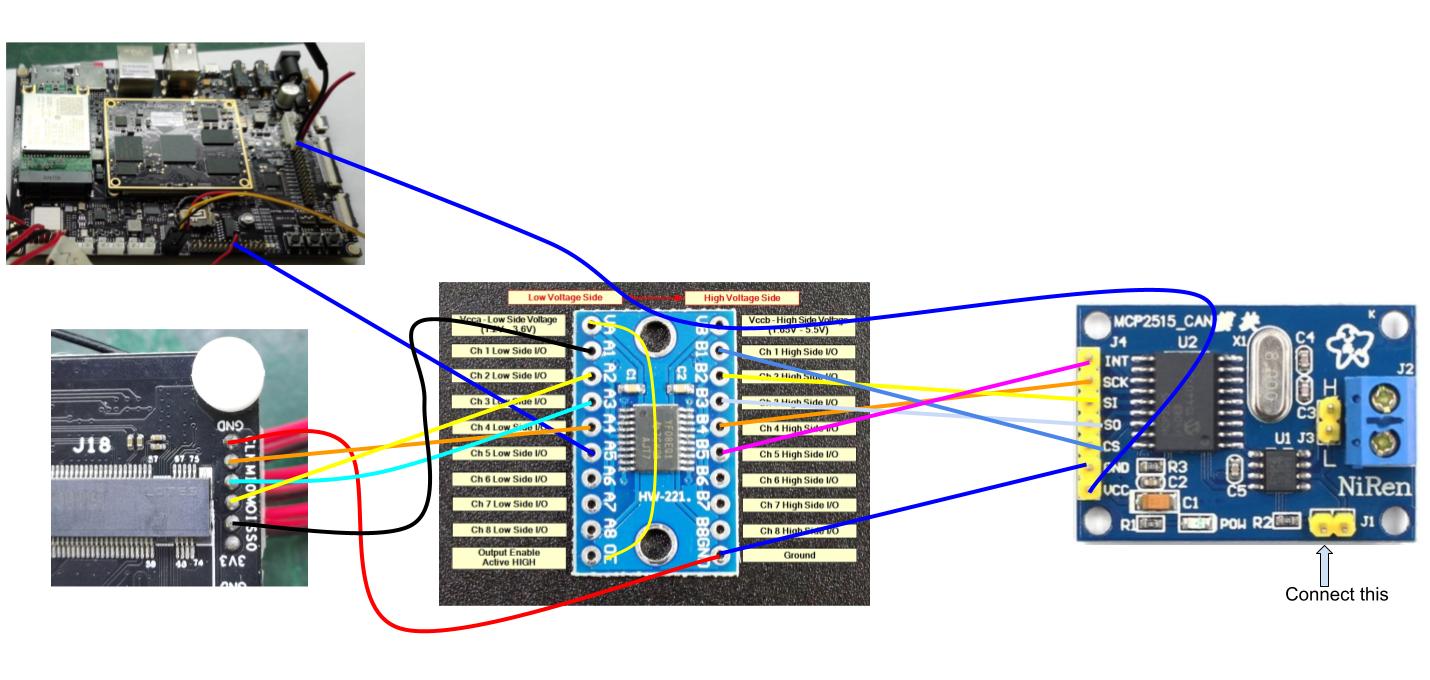
Also, split the supply voltage for both ICs.
If using this board, some small adjustments may be required, which might need soldering skills. Otherwise, you're good to go.
For more details, check out this forum thread:
Connecting the Module
To connect the module, use the SPI pin and one more pin for GPIO interrupt. Ensure that this GPIO pin is not allocated to other features.
| SN | MYD-C8MMX (ECSPI2, See back of the board) | ((bank - 1) * 32) + pin | MCP2515 |
|---|---|---|---|
| NA | J23-1: 3V3 | NA | VCC |
| gpio5.IO[13] | J23-2: ECSPI2_SS0 | 141 | CS |
| gpio5.IO[11] | J23-3: ECSPI2_MOSI | 139 | SI |
| gpio5.IO[12] | J23-4: ECSPI2_MISO | 140 | SO |
| gpio5.IO[10] | J23-5: ECSPI2_SCLK | 138 | SCLK |
| NA | J23-6: GND | NA | GND |
| gpio4.IO[10] | J16-14: SAI1_TXFS | 106 | INT |
1. Without level shifter connection
2. With High speed level shifter (TXS0108E)
So here hardware is done, now moving to software part
Linux Driver & Userspace Program
To get the system working, you need to understand two key aspects:
- Linux Driver Setup (Kernel driver, DTS changes)
- User Application Tools
1. Linux Driver Setup
In Linux, there are two types of drivers for CAN:
- Character device based drivers
- Network socket based drivers
I’ve used and preferred SocketCAN, which is the network socket-based driver. Specifically, I
worked with SAE J1939 and used hardware from Microchip: MCP251x.
Additional Resources
2. User Application Tools
I recompiled the Linux image and booted from the SD card. The new DTS changes and drivers are reflected in the boot process.
You can download the modified DTS file from the following link:
For the Linux config file, refer to the following directory:
Alternatively, check the source on GitHub:
Kernel Configuration and Compilation
To launch the kernel menuconfig, use the following command:
After making your changes, rebuild the kernel using:
My Linux Kernel Configuration for CAN Driver
This is my configuration for Linux/arm64 4.9.170 Kernel.
Menuconfig changes
Linux Kernel Configuration.
    [*] Networking support  --->
        <*>   CAN bus subsystem support  --->
            <*>   Raw CAN Protocol (raw access with CAN-ID filtering)
		    <*>   Broadcast Manager CAN Protocol (with content filtering)
		    <*>   CAN Gateway/Router (with netlink configuration)
		    CAN device drivers
			    <M> Virtual Local CAN Interface (vcan)
            <*> Platform CAN drivers with Netlink support
            [*]   CAN bit-timing calculation
            CAN SPI interfaces  --->
        		<M> Microchip MCP251x SPI CAN controllers
           	[*] CAN devices debugging messages
After these changes, recompile Linux, and load it into your hardware.
Debugging & Troubleshooting
We were using MYIR Tech development board (specifically MYC-C8MMX-V2)
1. Driver fails to initialize the MCP2515 CAN controller
root@myd-imx8mm:~# modprobe can
[ 25.901538] can: controller area network core (rev 20170425 abi 9)
[ 25.907887] NET: Registered protocol family 29

root@myd-imx8mm:~# modprobe can-dev
root@myd-imx8mm:~# modprobe can-raw
[ 25.948100] can: raw protocol (rev 20170425)

root@myd-imx8mm:~# rmmod mcp251x
root@myd-imx8mm:~# modprobe mcp251x
[ 26.274264] mcp251x spi1.0: Cannot initialize MCP2515. Wrong wiring?
[ 26.280681] mcp251x spi1.0: Probe failed, err=19

root@myd-imx8mm:~# echo "8 4 1 7" > /proc/sys/kernel/printk
root@myd-imx8mm:~# rmmod mcp251x
root@myd-imx8mm:~# modprobe mcp251x
[ 94.513452] mcp251x spi1.0: MCP251x didn't enter in conf mode after reset
[ 94.520300] mcp251x spi1.0: Probe failed, err=16
[ 94.525162] mcp251x: probe of spi1.0 failed with error -16

root@myd-imx8mm:~# ip link set can0 type can bitrate 125000
Cannot find device "can0"
root@myd-imx8mm:~# ip link set up can0
Cannot find device "can0"
root@myd-imx8mm:~# ip link show can0
Device "can0" does not exist.
root@myd-imx8mm:~# ifconfig can0
can0: error fetching interface information: Device not found
Reason for this failure can be:
- Incorrect Wiring
- Wrong Device Tree Configuration
- Power Supply Issues
- Clock Issues
- Driver/Kernel Incompatibility
The best way to troubleshoot this is to use a USB Logic Analyzer. Simply connect your SPI pins to the analyzer and check according to the CAN protocol if it is sending and receiving data.
2. Probe failed
----
J1939 & CAN-utils
Installation Steps for CAN-utils
Follow the steps below for installing can-utils. More details can be found at
elinux.org/Can-utils:
git clone https://github.com/linux-can/can-utils.git
cd can-utils
./autogen.sh
./configure
make
make install (with root privileges)
Bringing CAN Interface Up
Virtual Interfaces
SocketCAN also offer virtual CAN for testing purposed, with below cmds you can
sudo modprobe vcan
sudo ip link add dev vcan0 type vcan
sudo ip link set up vcan0
Native Interfaces
sudo ip link set can0 type can bitrate 125000
sudo ip link set up can0
Test CAN Device
ifconfig vcan0
Useful J1939 Resources
- J1939 Framework - GitHub
- J1939 Presentation (PDF) - Simma Software
- SAE J1939 Message Format - Copperhill Tech
- J1939-71 PDF Document
- J1939 PGN Conversion Tool - CSS Electronics
- J1939 PGN Spreadsheet
- J1939 Explained - Simple Intro Tutorial
- Didn’t read this: What is SAE J1939 (PDF) - Axiomatic
J1939Socket
Other Development Boards
Good Explanation on J1939
A detailed explanation on J1939 can be found at: